7.7 A Complex Model 2 Configuration Example

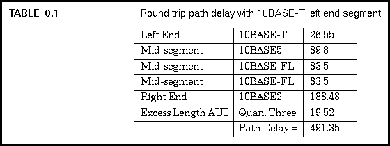
To complete the process, we need to perform a second set of calculations with the left and right segments swapped. In this case, the left end becomes a maximum length 10BASE-T segment, with a value of 26.55, and the right end becomes a maximum length 10BASE-2 segment with a value of 188.48. Adding the bit time values again, we get the following:
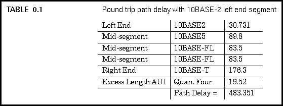
Since the second set of calculations produced a larger value, this is the value we must use for the worst-case round trip delay for this Ethernet. Finally, the standard recommends adding a margin of five bit times to form the total path delay value. We are allowed to add anywhere from zero to five bits margin, but five bit times is recommended.
Adding five bit times for margin brings us up to a total delay value of 496.35 bit times, which is less than the maximum of 575 bit times that is allowed. Therefore, our complex sample network is qualified in terms of the worst-case round trip timing delay. All shorter paths will have smaller delay values, so all paths in the Ethernet system shown in Figure 7.3 meet the requirements of the standard as far as round trip timing is concerned.
Generated with CERN WebMaker