7.5 10-Mbps Configuration Guidelines: Model 2
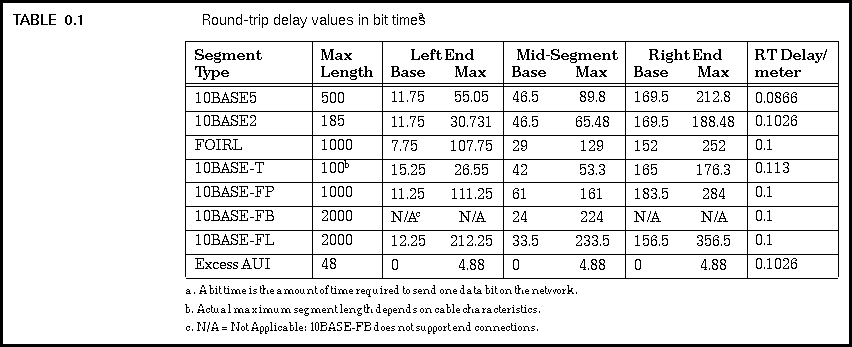
The way to verify that your Ethernet system meets the limits is by calculating the total path delay (round trip timing) of the worst-case path in your system. This is done using "segment delay values" which are provided in bit times for each segment type. Table 7.1*1 shows the segment delay values used to calculate the total worst-case path delay. 
To calculate the round trip delay value for each segment in your LAN, you multiply the length of the segment (in meters) times the delay factor listed in the last column of the table for the segment type, and add the result to the "Base" value for the segment in question. If the segment is at the maximum length, or if you're not sure of the segment length and want to use the maximum length in your calculations just to be safe, then instead of calculating the segment delay time you can simply use the "Max" value listed in the table for that segment.
Once you have calculated the segment delay values for each segment in the worst-case path on your LAN, you then add the segment delay values together to find the total path delay. To this total you add a margin of 5 bit times. If the result is less than or equal to 575 bit times, the path passes the test. The value of 575 bit times ensures that a DTE at the end of a worst-case path will not send more than 511 bits of the frame plus the 64 bits of frame preamble and SFD*2 (511 + 64 = 575) before the DTE is notified of the collision and stops transmitting.
If the path you are checking has left and right end segments of different segment types, then you must check the path twice. The first time through you use one of the segment types as a left end segment, and the second time you use the other segment type as a left end segment. The path must pass the delay calculations in both directions. We will show how this is done in the complex sample network later in this chapter.
Generated with CERN WebMaker